 |
505 Trim
of the World Champions 2003 |
 |
| Control/Wind | 0,5 - 1,5 (1-3 kn) |
2 (4-6 kn) |
3 (7-10 kn) |
4 (11-16 kn) |
5 (17-21 kn) |
6 (22-27 kn) |
| Mast rake [m] |
7,80-7,78 |
7,80-7,78 |
7,75 |
7,70-7,68 |
7,65-7,63 |
7,58-7,55 |
| Jib fairleads [cm] |
48 |
50 |
51-52 |
55 |
60 |
65-70 |
| Mast ram |
pull up totally, mast prebent |
pull up a little or neutral |
neutral or slightly down |
down, so that kicker power does not bend mast too much |
down |
down |
| Shrouds |
tight to prebent mast |
very tight *) |
not very tight, but must not be loose on lee-side |
a little more loose |
tight |
tight |
| Mainsheet triangle |
to windward |
to windward |
to windward, much power on mainsheet |
middle |
middle |
middle |
| Kicker |
sagging |
sagging |
no sagging, but still not tight |
a little |
tight |
tight |
| Centerboard |
totally down, a little forward, gybing |
totally down, gybing |
a little up, but still gybing |
5 degree back, not gybing |
10-15 degree back |
20 degree back |
| Outhaul |
max. tight |
open 1cm |
open 2cm |
tight |
max. tight |
max. tight |
| what else ... |
sit far to the front, jibsheet very loose, fairleads high - the jib has to be open in upper part! |
sit far to the front |
sit to the front |
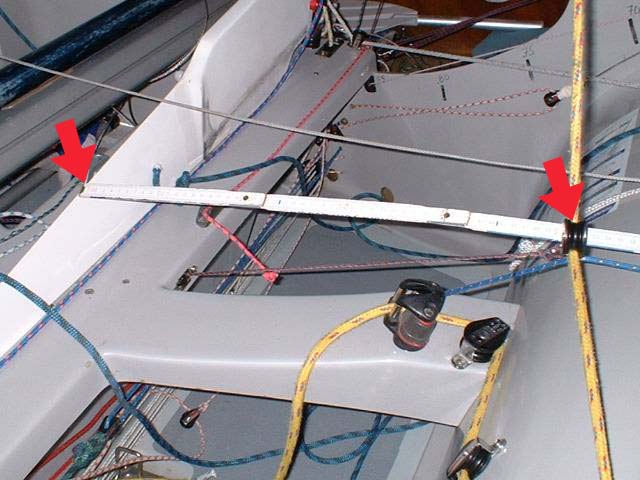
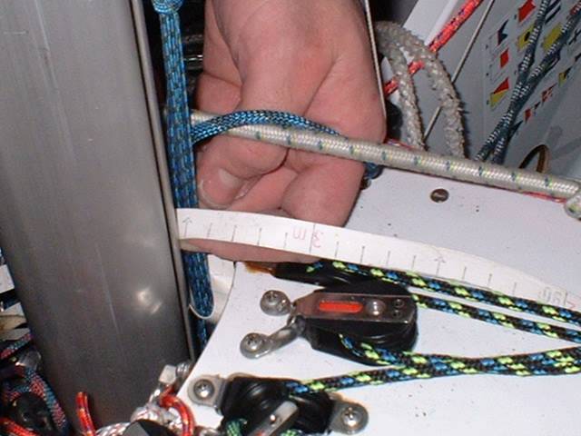
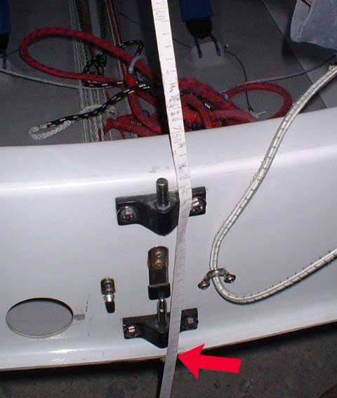 take measurement to the lower edge take measurement to the lower edge
|
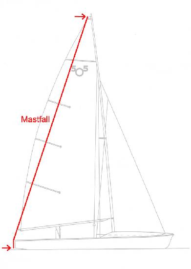 Mast rake Mast rake
|
| The mast rake measure has been taken from the top to the
lower edge of the transom. Connect the end loop of the tape measure to the
shackle of the main halyard. Then pull it up to exactly the same position
that you would use for the main sail. |
Note: Most tape measures have a few centimeters of
'dead end'. The scale does not begin exactly with the end of the tape. Also
be careful that the tape measure is really straight (not twisted) and you
don't have too much wind when taking measures. |
For reproducible results please take also the following into account:
| In general: the lower the weight of the crew (and
helmsman) the higher the mast rake when the wind increases (more mast rake
means = higher inclination = lower rake measure value). |
Note: some of you know the trim table from Ian Baker
from 1994. When you compare the Barker table with this table it's important
to know that the mast rake is measured differently. Ian Barker took the
measure from top to the inside of the boat (bottom / transom). The result
are values about 4 cm less than the ones in this table. Additionally the
mast was allowed to freely bend. Mast ram and boom had been removed . So
the mast has not been forced to be straight while taking the measures. |
 schema |
The jib halyard tackle should have a reduction ratio of
at least 24:1 (better 32:1). It should allow for the full mast rake range
of 7,80 m to 7,55 m (method as described above).
|
 how to measure |
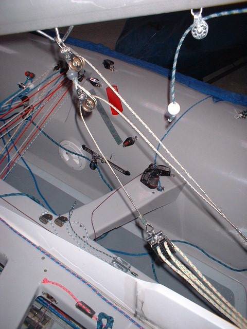
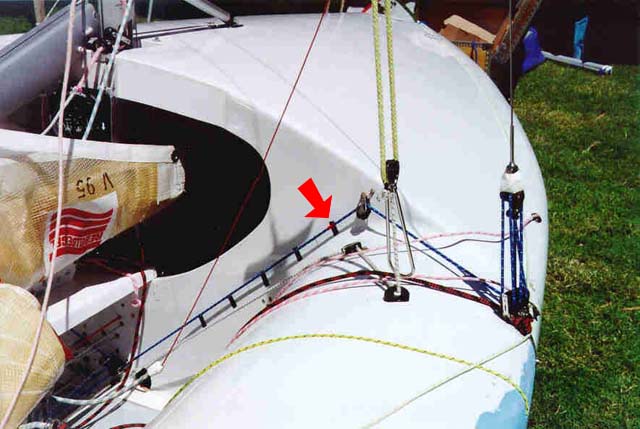
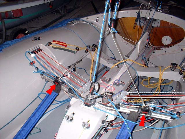
The jib lead position has been taken between centerboard
(middle of boat) and the block of the jib leads. It is important to have
an in/out and up/down control for the jib leads. It does not necessarily
need to look like the ones on the left photo. It can also be a combination
of a track for the in/out control and a barber for the up/down control like
the ones on the middle photo. |
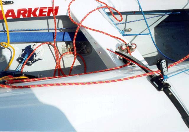 jib track and barber |
It is important that the jib fairleads can be used in a considerably
high position in light winds as described in the trim table to open the
jib in the upper part of the leech. Additionally the block of the jib sheet
has to be mounted far enough back to achieve a flat enough sheet angle.
Modern jibs like the BM jib have a very high clew. |
 sheet markings sheet markings |
Jib sheet markings are helpful to immediately find the old
position after tacking. A black felt-tip pen can simply be used if the sheet
is white.Otherwise apply a whipping of white yarn. |
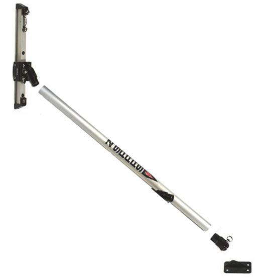 strut assembly  8:1 system |
The most effective mast controller is a strut. It is mounted
on the fore-deck and pulls or pushes on about the level of the gooseneck
and lower. A 8:1 tackle pulls down, a 2:1 tackle pulls up. |
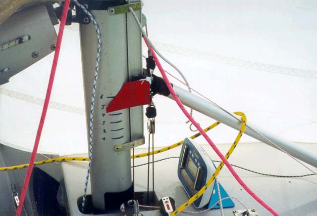 pointers |
Very helpful are two small pointers mounted on the traveller
car and markings on the mast (black felt-tip pen). Make markings corresponding
to the different mast rake positions. These positions
are called the "neutral positions". Example: lets assume you have marked
the mast rake positions "1" for "upright", "2" for "middle" and "3" for
"max. rake" and you have always pushed the mast straight. Then you automatically
get the positions for the "1", "2" and "3" markings for the mast ram. But
these positions are clues only. The position for middle wind and upright
mast is regularly a little bit down (more tight) and for heavy wind a bit
up (loose) compared to the neutral positions. |
 usage of mast ram |
With the mast upright the traveller should not be at the
upper end of the track allowing to be pulled up even more in light winds
. Pulling the mast ram up results in a prebent mast. Tight shrouds give
you additional bending at the height of the spreaders. The result is a flatter
main sail and an open leech. In the middle wind range power in the rig is needed. The mast ram's neutral position or slightly more pressure is used. This results in good pointing ability sailing upwind. What does neutral mean? This is the position corresponding to the current mast rake (though the measure taken with a straight mast). In heavy winds there is still power on the mast ram needed. This is important so that the kicker does not bend the mast too much and fulfills his real task: pulling the boom down. With more mast rake pull the mast ram down a little. But with a lightweight crew this should be only a tiny bit. |
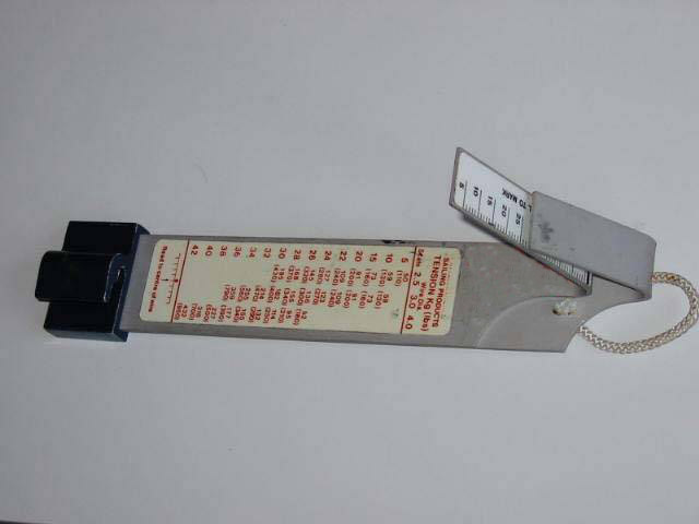 rig tension gauge |
The trim table gives you only a qualitative description
of the shroud tension. For those who still want to measure something: with
the SUPER SPAR gauge the tension "tight" means about 200kg. |
 schema |
The shroud tension control should have at least a reduction
ratio of 16:1. |
 markings |
Markings for the shroud tension control are very helpful.
If the control lines are lead along the bulkhead, the markings can be made
right here, like Christer Bergström did it (s. photo). |
The main sheet triangle decisively determines the angle
direction of draught of the main sheet.
|
|
 traveller car in mid position 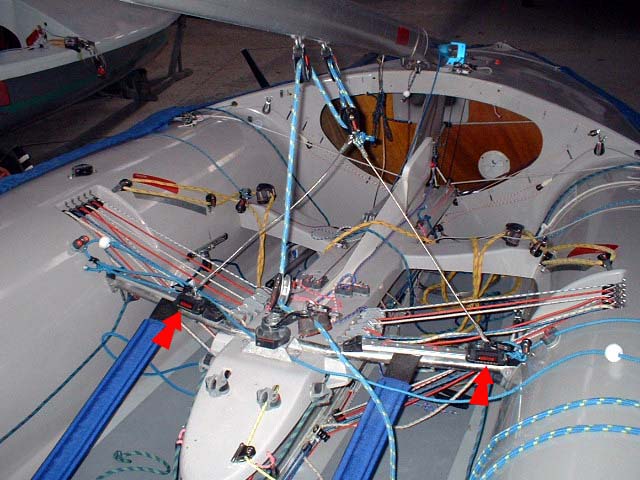 traveller car in weather position 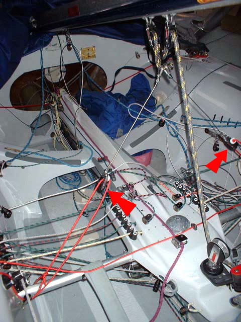 tackles in the middle 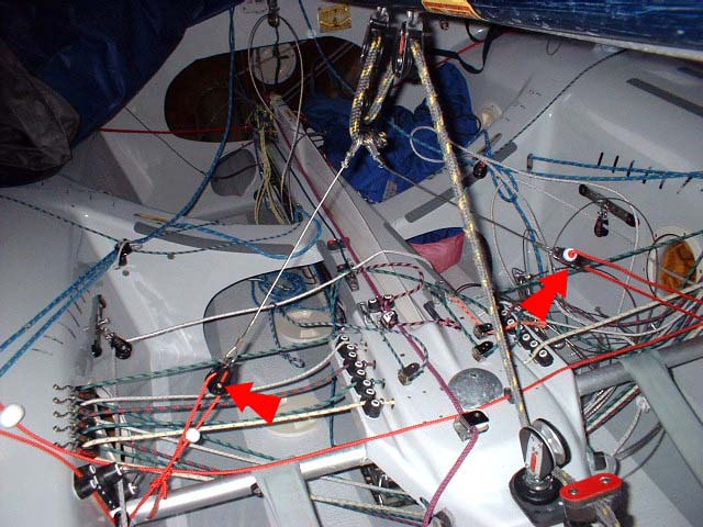 tackles to weather |
The pictures show the different types of mainsheet triangles
that are in use. The expensive solution with short traveller tracks has the advantage
that less power (in your arms) is needed. The simple version works with two 2:1 tackles. The rope stoppers have
to be adjusted in a way that with a totally eased triangle and upright
mast there can still be put medium tension on the main sheet. Nevertheless
it is not easy to find the right positions for the rope stoppers. If you make the triangle (the two legs) too short, then you can not pull
them enough to the weather side. If you make them too long, it's difficult
in medium winds to achieve enough tension on the leech (without also pulling
the lee side). Please look on the photographs and notice also how the end of the main sheet is fixed. To allow the two mainsheet blocks to come very close together (and the boom close to the centerline) there is no becket. The mainsheet goes directly through the (extra wide) hard eye of the short steel wires for the middle block. The mainsheet is then fixed with a figure eight knot. |
 schema |
A good kicker should have a reduction ratio of at least
16:1. It is also very important to have a wide control range. With the main
sail open it should be possible to ease the kicker until it's completely
loose. On the other hand you must be able to pull it tight with maximum
mast rake. |
| A cascading kicker system like the one on the left photo
is a perfect solution. A lever based system would not be ideal because of
the small adjustment range. |
| Every boat has two "wings". One above water - mainsail and
jib work together as one - and another in the water - the centerboard (working
together with the rudder). Both are exactly of the same importance (and
nearly as expensive)! The centerboard should be reworked at least once a season and all scratches and kinks carefully removed. In particular the leading edge and the first 2-3cm of the section must not have any noticeable unevenness or groove. |
|
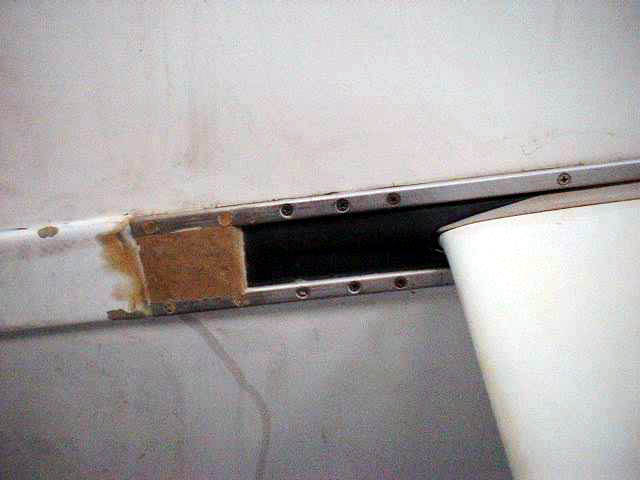 rubber gasket |
The slot gasket has to be strong enough to provide
a really good sealing. The best material is a folded double layer of sailcloth.
The overlap of the two gaskets has to be different according to the needs:
the overlap is zero in the front part and a few millimeters in the
back part of the trunk. The hole in front of the centerboard should be sealed
with an additional rubber gasket. |
| With increasing winds
the centerboard has to be raised more and more. This causes the center of
effort to move aft and correspond better to the center of effort of the
sails (with more mast rake). And additionally this moves the center of effort
up, so that the boat can more easily be kept upright. It's reasonable to
have markings for some positions on the centerboard (black felt-tip pen,
possibly even different colors): |
|
|
|
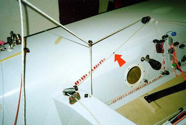
 centerboard angle |
The vertical (all the way down) position should be marked
very carefully. This position is special: it's the one with the least drag
(in relation to the lift. The lift/drag ratio determines the pointing
ability). How this and some other positions can easily be found is shown in the left drawing. |
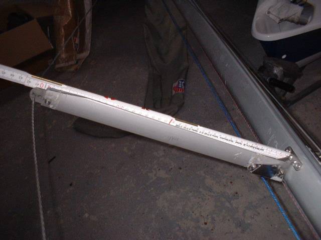
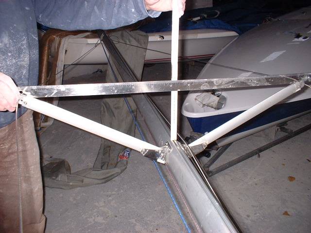
 centerboard position |
The centerboard position has
to be measured from the aft edge of the transom to the 30% line of the centerboard
section. The position of the bolt is irrelevant. To compare the position of two centerboards, it is important to compare the positions of the center of effort of the two centerboards. The center of effort of a vertical centerboard is always between 25-35% of the section chord (width of the centerboard). To make it simple we calculate with 30% now. Ok, how do we compare the position of centerboards with different widths? Put the boat on the side, centerboard perpendicular to the bottom and measure the width. Determine and mark 30% of the width. Then measure the distance to the aft edge of the transom. |
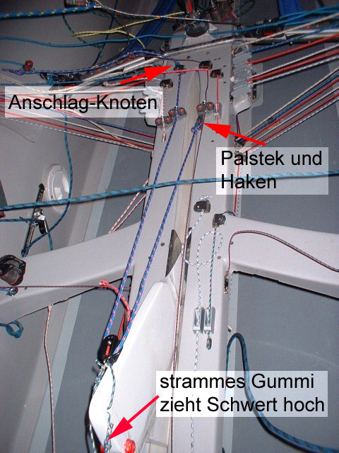 centerboard halyard |
The arrangement on the left photo has been proven to be a
very good solution for the centerboard control line. Namely the centerboard
moves on its own to the reaching position once the control line is out of
the cleat. This is supported by a strong elastic. This mechanism allows
you to ease the control line while you are still approaching the weather
mark. The centerboard stays down until you bear off and then it moves up
on its own. To raise the centerboard totally, the end of the control line has to be unhooked. |
| spreader length | 415 mm |
| spreader angle | 148 mm |
| spreader height |
3050 mm |
| mast position |
3048 mm |
| shroud plate position |
2320 mm |
| head stay position |
4780 mm |
| centerboard position |
2500 mm |
 measure the spreader length |
The spreader length measure
is taken from the shroud wire to the side of the mast section. A lightweight
crew can use shorter spreaders (410 or 405 mm). The same is valid for a
crew with average weight and more wind (see crew weight ). |
 measure the spreader angle |
To take the measure for the spreader angle put a ruler on the shroud
wires and measure the distance to the mast slot. To eliminate the looseness
in the spreader bracket, press the spreaders up to the load position beforehand!
|
| The spreader height is the measure
from top of deck to the spreaders. This is always the same for all SUPER
SPARS masts (bought at Segelsport Jess). |
 positions overview |
Mast and shroud plate positions
determine spreader angle and spreader length. Spreaders and shrouds are
a rather complex system. Strictly speaking none of the measures can be looked
at on its own. It is important that you think about these interdependencies
before applying the measures to your own boat. If e.g. the shroud plates
are not exactly at the same position, then you cannot directly compare the
spreaders length and angle! The position of the shroud plates is measured from the fore stay. The headstay position is measured from the transom (aft edge). |
 mast position |
The mast position measure is taken
from the aft edge of transom to the aft edge of the mast section. The measure
in the table (3048) is the smallest allowed value (most aft). |
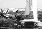
 light winds |
With light winds its important to trim your weight far forward
to avoid dragging at the transom. To achieve this the helmsman usually must
sit in front of the main sheet triangle. Some people even use plexiglas
flaps for the drain holes in the transom to exactly see whether they sit
far enough forward. You can see the bubbles very well.. |
 medium wind range |
In the medium wind range and with few waves it is important
to use the maximum waterline length to achieve the highest possible pointing
ability. The bow has to be in the water until to the very fore located part.
The crew can see this very well from the trapeze. The crew eventually has
to stand with one feet even in front of the shroud wire and walk fore and
aft to avoid to hit the bow too deep into the waves. |
 upper wind range |
In the upper wind range the boat trim should be further aft
to allow surfing more easily. The same is right for medium winds and waves
in the open see. |